« 研究集会感想からアクティブな知覚へ:コメント返答 | 最新のページに戻る | アンケート集計 / 来年は「身体性の脳内メカニズム」です! »
■ A three-choice reaction time task using Arduino
I have been using Facebook for a while. I imported my blog and it works ok. Now I decided that I will occasionally post some entries in English.
Recently I made a simple reaction time task using Arduino. So it will be a good material to write in English because it may interest English-speaking readers.
Arduino is a set of hardware (with AVR microcontroller) and software (IDE with a simple, C-like language) for physical computing. It is very cheap ($30 hardware and free software) and is very easy to start. If you have an LED, you can run a program to blink the LED within 5 min.
I have been interested in physical computing. But the PIC, the most popular microcontroller, was too difficult for me, with a complicated, assembler-like language.
Recently I read some issues of MAKE magazine and know what arduino is. I bought Arduino Duemilanove, just as a hobby, and played around for a while. I noticed that I can use it for a simple reaction time task, which would be usually built on DAQ + LabView, Matlab or TEMPO. So I started and this is the preliminary result.
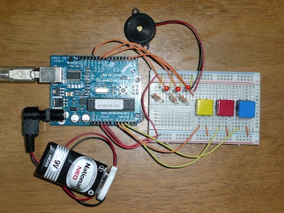
As in the figure, Arduino Duemilanove is connected via an USB cable to my PC. A 006P battery is also connected. It works standalone when detached from the USB cable. All of the other parts are plugged into a solderless breadboard. It has three LEDs. From D9-11 pins, an LED and a resistor (330 Ω) are serially connected to the GND pin. A small speaker is connected between the D3 pin and the GND pin. Three buttons are connected between the A0-2 pin and the GND pin.
Now I start arduino IDE on the PC and upload the program 'Reaction_time2.pde'. here is the code. The code is based on a sample program on the arduino web site (Reaction Time Tester).
Then detach the USB cable. It will run standalone. Start the task by pushing the middle button. Then three LEDs flashes. After a variable delay (defined by iti_min and iti_max), one of the LED turns on. Your task is to push the correct button (left button for left LED and so on) as early as possible. If you choose the correct one, the LED turn off with a high tone. If you choose the incorrect one, the LED does not turn off, with a low tone. After 10 trials, three LEDs flashes again and the task terminates.
After the task, reconnect the USB cable and run the program 'Read_score2.pde', which is actually a subset of the 'Reaction_time2.pde'. Here is the code. Then you will get a result like that on the serial monitor of the IDE:
Begin
Ready
0 3 959 1
1 1 939 1
2 1 515 1
3 2 530 1
4 3 914 1
5 1 510 0
5 1 732 1
6 1 507 1
7 3 518 1
8 1 434 1
9 2 422 1
56
Completed
The first column: trial number; the second column: target number; the third column: reaction time in ms; the fourth column: correct (=1) or incorrect (=0).
There are a lot of rooms for improvement but I am happy that it looks good enough for replacing some of otherwise bigger systems.
